The Importance of Timing
Welcome. In this post, we’ll cover what a clock is in the context of a processor, why they’re important and a natural first step, and how to build one.
Synchronization and Control
When we took a look at some basic logic circuits, I mentioned that the outputs of our example circuits were a direct and (almost) immediate function of the corresponding inputs. This is fine in some cases, but it means that we have no way of maintaining real state: no way of persistently storing the results of computation, and no options for sequencing actions in the processor. All the components are working asynchronously, so if we continued to build a processor like this, we’d have a hard time predicting how everything would interact and verifying that everything is working properly.
To solve this problem, processors usually include some sort of clock module. These clock modules generate a simple square wave:

This wave alternates between LOW (0v) and HIGH (5v, in our case). If we think about control signals - signals to individual modules of the processor that control things like input/output enable (whether or not we should read from/write to the bus) - we can use this square wave to determine when those control lines should actually be active. We can do this by AND’ing the control signals with the shared clock signal, and using that to drive the modules.
This gives us control over how the current state of the processor progresses over time. When the clock signal is LOW, the state of the processor doesn’t change. During this time, we could set as many control signals to HIGH/LOW as we want, but until the clock signal goes HIGH, there won’t be any change in state.
Since the main action happens when the clock signal goes high, a faster clock (more HIGH/LOW transitions per second, measured in Hertz) results in a more performant processor. Many of the 74 series chips we’ll be using have a clock input pin, so hopefully it is clear why the clock is a good place to start.
Clock Requirements
Aside from generating a square wave, what other features might we want out of a clock module? An easy one is the ability to stop the clock. There will be situations in which being able to halt the clock and observe the state of an individual module or the processor as a whole will come in handy for troubleshooting. Another must is the ability to adjust the speed of the clock. We’ll want the freedom to watch a program execute at a human-readable speed (very slow), but retain the ability to have the processor run as fast as it can. Finally, we’ll want some form of debug mode that allows us to generate one clock pulse at a time when we press a button.
555 Timer
The 555 timer is an extremely popular chip that can satisfy all of these requirements. There are a lot of great resources that describe the inner workings of the 555 timer, so we won’t cover that here. Depending on how you wire the chip up, it can run in one of three modes: astable, monostable, and bistable. Astable is the one we want, as it produces a square wave. Below is a fairly standard setup pulled from here. Translating that to our breadboard:
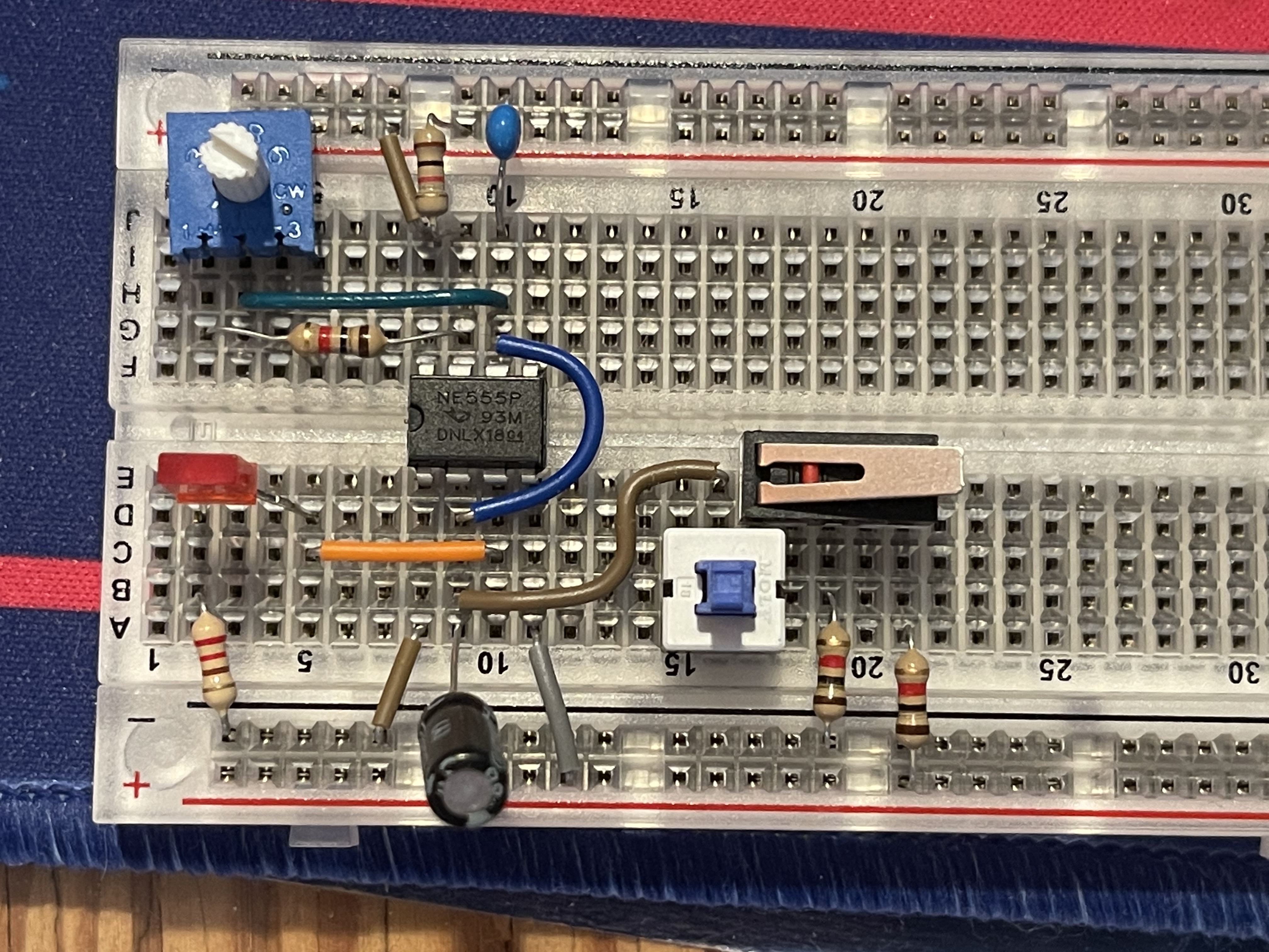
I’ve added a few things from a great video on the topic
First, the dial to the left of the chip is called a potentiometer. These function as variable resistors, meaning we can change the resistance value connected to pin 6 of the 555, which adjusts the frequency of our clock.
To the right of the chip, there are two switches. The white and blue one stays down when you press it. Depending on whether or not the button is depressed, i’ltl either connect the middle pin (brown wire) to the left or right pins of the switch. The switch right next to it is connected to its left pin, and features both normally open and normally closed contacts.
Brief note on normally open/normally closed contacts
If a switch is normally closed, that means the circuit is normally complete, until you press the switch, at which point the flow of current is cut off. This is like an inverted version of the pushbutton switch we looked at in the transistor post. That sort of switch has normally open contacts, meaning that current can’t flow until the switch is pressed.
The switch with that lever has three pins. Common, normally closed, and normally open. Any signal connected to the common pin will be routed through the normally closed contact until the switch is pressed, at which point the normally closed contact cuts off, and common connects through the normally open pin.
So, when the first switch is depressed, it connects the capacitor on pin 2 of the 555 timer (critical to the chip’s astable mode) to the common pin of the second switch. The normally closed pin of the switch is tied to ground, which essentially shorts the whole charge/discharge method that the 555 timer uses. This stops the clock from running. Pressing the switch connects common (which connects to pin 2 of the 555) to 5v, and brings the output high. Here it is in action:
So now, we’ve satisfied all of our immediate requirements. We have a circuit that produces a square wave, features adjustable speed, and can be stopped and single-stepped to produce individual clock pulses. This wraps up the clock module for now. Later on, we’ll likely revisit this board to add things like an actual halt signal that can be controlled without a button, as well as an inverted clock output.
Thanks for reading this far. This post had a lot of hand waving, but hopefully the main ideas behind our clock are still clear. In the next post, I’ll talk about registers and the program counter.
jc