Processor Project Log 1: Background
Welcome, this is the first post discussing my current project: building a processor out of TTL integrated circuits. I’ll cover a bit of background on the subject matter, and what is involved in a project like this.
disclaimer: I’m not - by any means - an expert on this stuff. I’m exploring these topics as a learning experience, and any explanations I present are as I understand them, which could be totally wrong/misguided
Some Project Background
What even is a central processing unit (CPU)?
A CPU is to a computer as a brain is to any animal. The brain is the center of control: it is responsible for decision making, receiving sensory input (sight, touch, taste, etc.), and sending signals to the rest of the body.
Similarly, a CPU is responsible for decoding and executing instructions, as well as sending/receiving data and control signals to external devices, like peripherals (keyboards, mice, devices you plug in), memory, the GPU, etc.
Hopefully this analogy is pretty clear - both are the primary workhorses of their respective systems.
How Could You Make One?
Generally, there are a few components that make a processor tick. Let’s say we want to tell a processor to add two numbers, A and B. Without getting bogged down with too much detail (yet), what circuits do we need to make that happen?
A way to make it do anything
First, we need a way to actually direct the processor to do something, which in our case is “add these two numbers.” The first step is to translate this operation into a format the computer can understand - an operation in such a format is called an instruction.
Instructions are a binary representation of the basic operations a processor can perform. Operations like moving/copying data, arithmetic, and control flow can all fall under this category. They tend to be encoded in the CPU itself, and together are called an instruction set
Instructions are generally made up of an opcode, which (arbitrarily) designates the operation we want to perform, followed by the operands needed for the operation. For example, if we pick 0100 as the opcode for “add,” and let A=8 and B=5, the instruction could look something like this:
0100 1000 0101
In reality, the operands are often memory addresses, which amounts to asking the processor to “add the value at memory location A to the value at memory location B.” For this example, it makes little difference.
Now we have what we need to tell the CPU what work we want it to do, but there’s another step required before it can actually do the work. The instruction needs to be decoded into control signals that tell the other components what they should be doing. More on these later.
Somewhere to put A and B
We need somewhere to hold data that we plan to use again in the near future. We’re passing the processor some operands, and it needs to store those operands somewhere useful. These are called Registers, and they’re where you put data used for calculations or that you might otherwise need to manipulate. Registers generally don’t hold much data, but can be read from/written to much faster than memory that’s external to the processor’s design.
Something that knows math
Now that we have the data stored somewhere useful, and the processor knows what needs to be done, we need something that can do basic arithmetic. This is called the Arithmetic Logic Unit or ALU. The ALU can perform mathematical and logical operations on (binary) integers, so we’ll need one of those if the processor is to do anything useful.
Getting programs and displaying results
We need some sort of I/O, input for feeding the CPU instructions, and output for presenting the results of a program (or intermediate results during execution). Ideally the output would be in a format easier for us to read than binary, but we can put that off until the end, since it just amounts to a mild inconvenience and doesn’t need to be factored in to the overall design.
The plan?
The plan is to implement the various necessary components of the processor out of logic gates using various 74xx series chips.
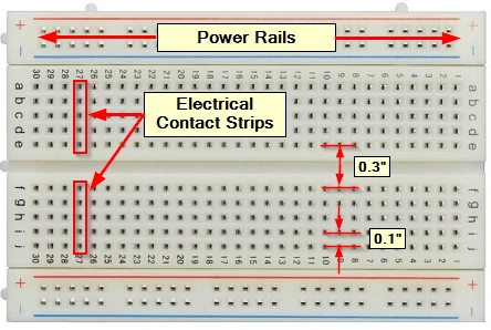
To prototype these circuits, I’ll be using solderless breadboards like these (image source):
I still have most of the design decisions ahead of me, so my progress thus far amounts to experimentation and discovery. I’ll talk about 74xx series IC’s and the decisions that need to be made in a following post - thanks for reading B-)